Become a member of our Forum, and gain access to a lot more information!
Become a member of our Forum, and gain access to a lot more information!
|
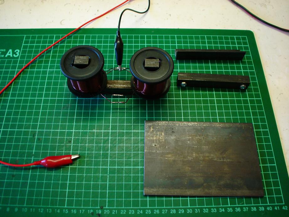
Flux Gate Magnetometers or Magnetic Induction Compass.Here we see a beautiful device. We see many variations and the best thing is that they work by simply moving ElectroMagnetic Flux. They are also very simple devices. Some pictures to give you an idea on the construction: Parallel core magnetometers, Vacquier configuration shown on the left and Foster configuration on the right:
Ring Core sensor developed jointly by the Naval Ordnance Laboratory and NASA Ames Research Center:
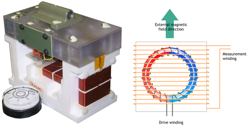
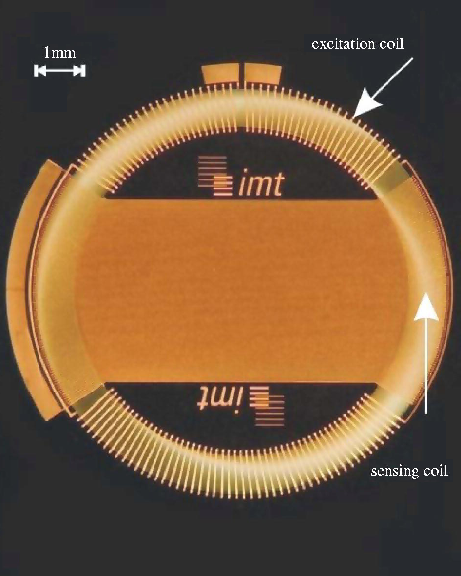
How a Fluxgate WorksFluxgate sensors are typically ring cores of a highly magnetically permeable alloy around which are wrapped two coil windings: the drive winding and the sense winding (as shown in the figure). Some sensors will also have a third feedback winding, if the sensor is to operate in closed loop. 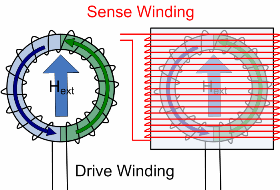
It is helpful to think of the ring core as two separate half cores shown in blue and green in the figure. This ring core is set up to measure the field in the direction of Hext. As the current flows through the drive winding, one half core will generate a field with a component in the same direction as Hext and the other will generate a field with a component in the opposite direction as Hext. DRIVE WAVEFORMAn example drive waveform is shown in Figure 2a.; The transitions are infact more 'square' than shown in the figure, here they are exaggerated to emphasize what is happening in the 2 half cores. No external fieldIn the absence of an external field (Hext= 0) the two half cores go into and come out of saturation at the same time. The fields generated exactly cancel out as shown in Figure 2b and there is no net change of flux in the sense winding, and hence no voltage induced. With external magnetic fieldWhen there is an external field, the half core generating a field in the opposite direction of the external field (for first transition in Figure 2c, shown in green) comes out of saturation sooner and the half core in same sense as the external field comes out of saturation later. During this time the fields do not cancel out and there is a net change in flux in the sense winding (shown in black). According to Faraday's law, this net change in flux induces a voltage, shown in black in figure 2d. Similarly towards the end of the transition, the half core now generating a field in the same direction as Hext goes into saturation sooner. Consequently, there are two spikes in voltage for each transition in the drive and the induced voltage is at twice the drive frequency. Measuring the fieldThe size and phase of the induced spikes tells us about the magnitude and direction of the external field. To help amplify this signal to make it easier to detect, the fluxgate magnetometers produced by Imperial College use a capacitor to tune the sense winding. The tuned sensor waveform is shown in red in Figure 2d. 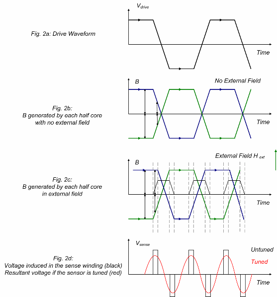
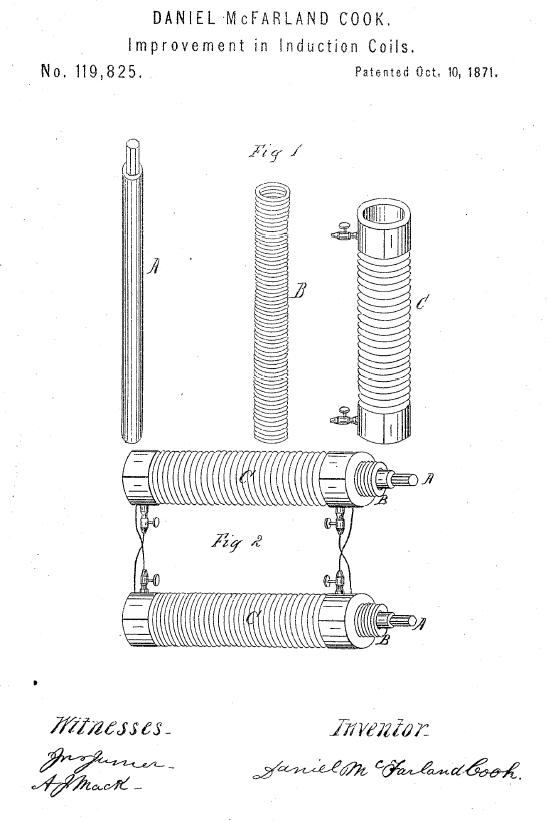
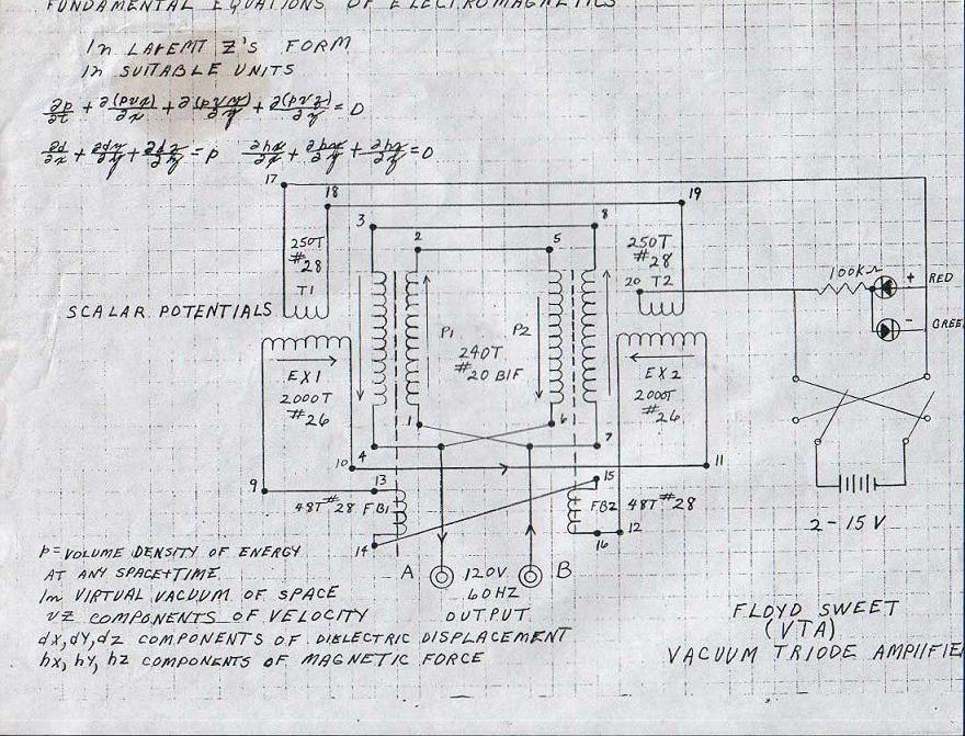
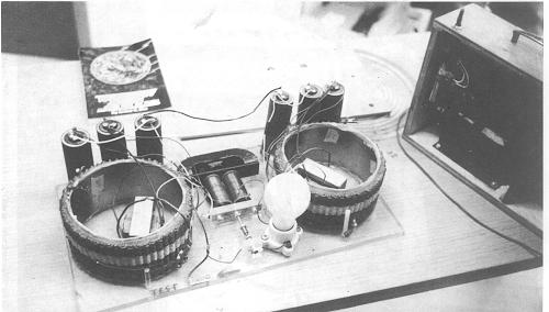
Ref: Imperial College Now lets have a look at our geometries and see if we can see any similarities:
Certainly we can see some similarity's here, and maybe the actual operational characteristics are similar to?
|